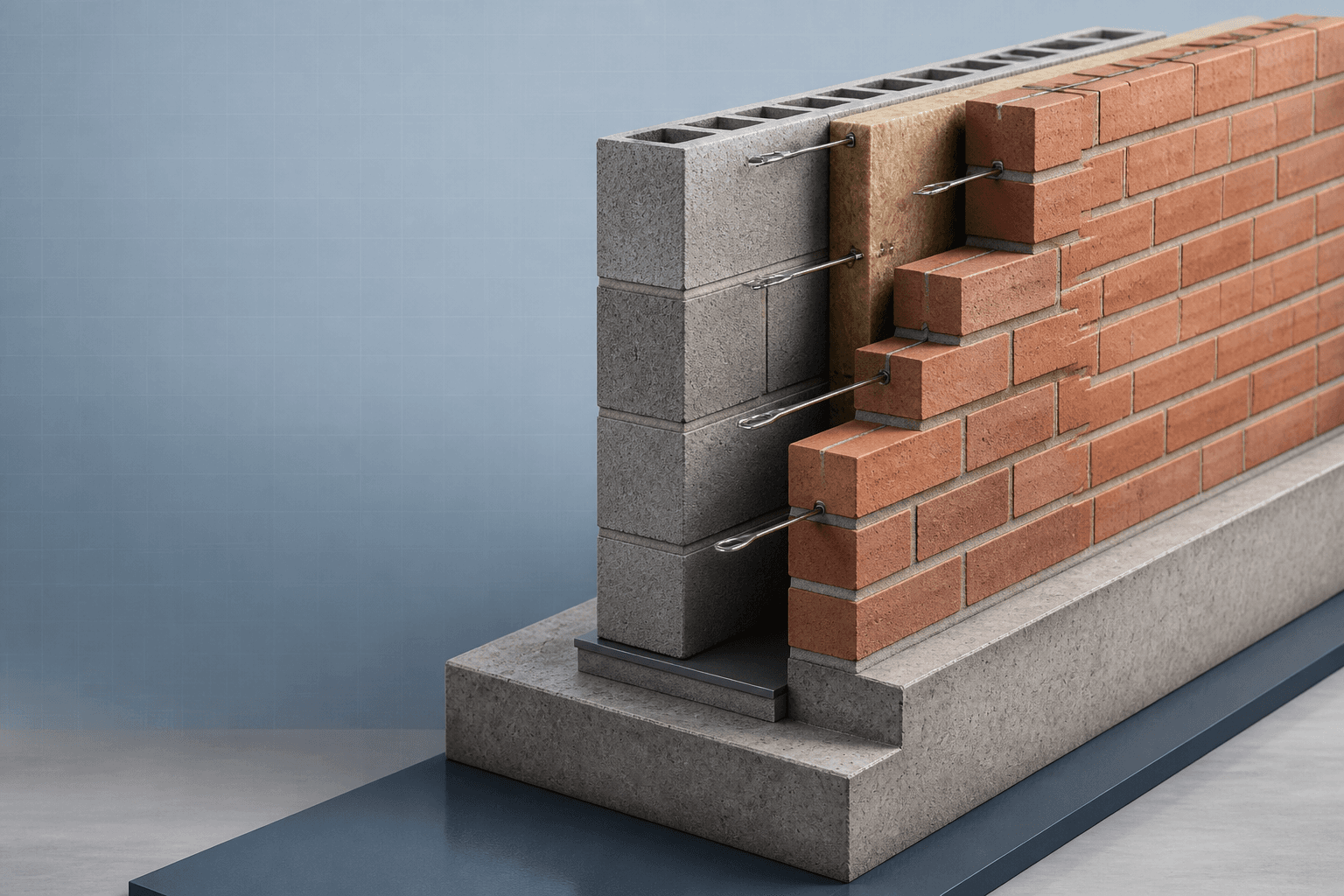
After this chapter, you should be able to
- Identify the structural parts of a cavity wall.
- Explain tie-mediated lateral transfer.
- Calculate source effective thickness and load share.
- Check tie spacing, force and utilisation.
- Recognise detailing that invalidates simplified design.
6.1 Purpose and main warningSource §6.1
A cavity wall is a system of leaves, ties, cavity, DPCs, openings, movement joints and workmanship. Its structural model must match the connection and detailing actually provided.
6.2 NotationSource §6.2
| Symbol | Meaning | Unit |
|---|---|---|
| t₁, t₂ | Leaf thicknesses | mm |
| t_ef | Effective thickness for vertical/slenderness assumptions | mm |
| W_Ed | Design lateral pressure | kN/m² |
| s_v, s_h | Vertical and horizontal tie spacing | m or mm |
| A_tie | Tributary area per tie | m² |
| F_tie,Ed / F_tie,Rd | Tie design force / declared design resistance | kN |
| M_Ed / M_Rd,total | Design moment / total simplified resistance | kNm/m |
6.3 Cavity-wall behaviourSource §6.3
- Vertical resistance assumption
- Both leaves contribute only when properly tied and the vertical load path justifies it.
- Lateral load assumption
- Wind may be shared between leaves, but transfer depends on tie capacity, spacing, stiffness and edge detailing.
6.4 Effective thickness for vertical resistanceSource §6.4
Do not use when one leaf is inadequately tied, acts only as veneer, or has an incompatible structural role or material behaviour.
6.5 Wall ties and lateral load pathSource §6.5
Wall ties transfer lateral action and help the leaves behave as a system. Tie type, declared resistance, corrosion resistance, spacing, embedment, slope and additional ties at discontinuities all affect the design assumption.
Use actual tie spacing in metres for area in m².
Compare with declared tie design resistance for the actual cavity and installation conditions.
6.6 Lateral load sharing between leavesSource §6.6
Useful for learning only; verify material stiffness, supports, openings, movement joints and tie transfer capacity.
6.7 Detailing checks before calculationSource §6.7
| Item | Why it matters | Design warning |
|---|---|---|
| Wall ties | Transfer lateral load | Increase density or use reviewed resistance where utilisation is high. |
| DPC | May reduce friction and transfer | Do not assume full continuity across a weak slip plane. |
| Openings and edges | Create unsupported zones | Add ties and check local pier/head/sill zones. |
| Movement joints | Break continuity | Treat as free or weakened edges. |
| Chases and recesses | Reduce thickness and strength | Include significant reductions in checks. |
| Durability | Controls tie material and corrosion risk | Select for cavity width and exposure. |
| Workmanship | Controls realised capacity | Verify embedment, spacing, slope and bedding. |
6.8 Cavity Wall and Tie CheckerSource §6.8
Cavity Wall and Tie Checker
Calculate tie density/demand, effective thickness, stiffness-based pressure split and a simplified combined flexural check while retaining detailing warnings.
- Inputs
- Leaf thicknesses · Tie spacing · Design pressure · Tie resistance · fₓₖ₂ · Material factor · Span · Bending coefficient
- Outputs
- Tie density · Tie demand/utilisation · Effective thickness · Leaf pressure shares · Moment demand/resistance · Flexural utilisation
- Status states
- Pass with detailing warning · Fail · Invalid input
- Validation
- Approved against the supplied worked-example results; project-specific verification remains required
Cavity Wall and Tie Checker
Approved educational implementation reproducing the supplied source example.
Tie demand and the simplified combined flexural check pass for the entered teaching assumptions.
- Tie density
- 2.78 ties/m²
- Tie demand
- 0.385 kN
- Tie utilisation
- 0.51
- Effective thickness
- 127.59 mm
- Leaf pressure share
- 0.555 / 0.515 kN/m²
- Flexural utilisation
- 0.86
Calculation trail
A_tie = 0.45 × 0.80 = 0.36 m²F_tie,Ed = 1.07 × 0.36 = 0.385 kNt_ef = ∛(t₁³ + t₂³) = 127.59 mmM_Rd,total = 1.392 kNm/mM_Ed = 1.204 kNm/m
6.9 WE-07 — Cavity wall and tie checkSource §6.9
WE-07 · MAS-WE-07 · Rev. C
Check a 102.5 mm outer leaf and 100 mm inner leaf under WEd = 1.07 kN/m2, with ties at 450 × 800 mm and declared tie resistance 0.75 kN.
- Tie density
n = 1/[0.45(0.80)]
2.78 ties/m2 - Tributary area
Atie = 0.45(0.80)
0.36 m2 - Tie force
Ftie,Ed = 1.07(0.36)
0.385 kN - Tie resistance
utie = 0.385/0.75
0.51 · PASS - Effective thickness
tef = ∛(102.53 + 1003)
127.6 mm - Pressure split
Use thickness-cubed stiffness proportions
0.556 / 0.514 kN/m2 - Flexural strength
fxd2 = 1.10/2.70
0.407 N/mm2 - Combined modulus
Ztotal = 1000/6(102.52 + 1002)
3.418 × 106 mm3/m - Resistance
MRd,total = 0.407(3.418 × 10⁶)
1.392 kNm/m - Demand
MEd = (1/8)(1.07)(3.02)
1.204 kNm/m - Verification
uM = 1.204/1.392
0.86 · PASS
Result. Tie demand and the simplified flexural check pass for the source assumptions. Final design must confirm support, durability, tie type, openings, movement joints, embedment and edge details.
6.10 Chapter summarySource §6.10
Key points
- A cavity wall is a tied wall system, not a solid wall by default.
- Tie density, demand, resistance, durability and installation all matter.
- Load sharing requires compatible leaf stiffness and reliable force transfer.
- Numerical adequacy must not hide uncertain detailing.
Source references recorded by the supplied chapter
- EN 1996-1-1 Clauses 5.5.1.3, 6.3.3, 6.5 and 8.5.2.2
- UK National Annex tie-density guidance
- EN 845 manufacturer tie declarations
- Masonry Note Part 1 and updated interactive book Chapter 06