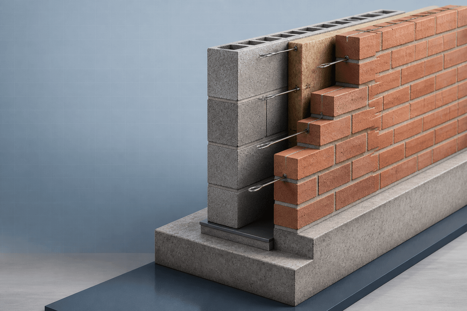
After this chapter, you should be able to
- Connect vertical and lateral checks.
- Distinguish helpful and harmful compression effects.
- Calculate source reduction and resistance values.
- Review biaxial action in both principal directions.
- Report the governing utilisation without double-counting.
7.1 Purpose and design questionSource §7.1
External loadbearing walls, narrow piers and strips beside openings may resist vertical compression and lateral bending together. This chapter connects the separate vertical and lateral checks into one reported design sequence.
7.2 Combined loading conceptSource §7.2
- Harmful effect
- Eccentric vertical compression reduces resistance through the capacity-reduction factor Φ.
- Potentially helpful effect
- Limited precompression may improve apparent flexural resistance where the applicable EC6 route permits it.
7.3 Load combinations and critical casesSource §7.3
Select the combinations controlling compression, flexure and the critical wall face. Treat favourable permanent load carefully and report both the governing utilisation and the governing design reason.
Confirm project-specific EN 1990 and National Annex combinations before real design.
7.4 Eurocode-style design routesSource §7.4
- Route A — Stability/eccentricity
- Convert lateral action to eccentricity and check vertical resistance.
- Route B — Flexure with permitted precompression
- Check flexural resistance using only the allowed compression benefit.
- Route C — Interaction review
- Review axial and moment utilisations together and identify the governing direction.
7.5 Key equationsSource §7.5
Φ reflects the applicable eccentricity and slenderness reduction.
Use consistent units and include required initial or accidental eccentricity terms.
The coefficient, span, failure direction and section modulus must match the selected model.
Use only where the applicable route and load combination permit this benefit.
A complete interaction rule may be required; do not infer universal adequacy from a simple maximum alone.
7.6 Biaxial bending and interactionSource §7.6
Masonry piers can bend about both principal axes because vertical load may be eccentric in two directions while wind acts on the wall. A design point well inside an approved interaction curve has reserve; a point near the curve is sensitive to small action or eccentricity changes; a point outside requires redesign.
7.7 Combined Wall/Pier Utilisation CalculatorSource §7.7
Combined Wall/Pier Utilisation Calculator
Combine source-example axial load, eccentricity reduction and limited flexural precompression into a transparent teaching summary.
- Inputs
- Pier width/thickness/height · Height factor · G_k/Q_k · Two eccentricities · Material strengths/factor · Reviewed Φ_mid · Selected M_Ed · Precompression limit
- Outputs
- N_Ed · Effective height · Φ values · N_Rd · Vertical utilisation · Moment resistances · Flexural and governing utilisation
- Status states
- Pass · Fail · Invalid input
- Validation
- Approved against the supplied worked-example results; project-specific verification remains required
Combined Wall/Pier Utilisation Calculator
Approved educational implementation reproducing the supplied source example.
The source-example pier passes the teaching-level combined check.
- N_Ed / N_Rd
- 90.00 / 121.73 kN
- Governing Φ
- 0.772
- Vertical utilisation
- 0.74
- M_Rd,x / M_Rd,y
- 1.51 / 3.08 kNm
- Flexural utilisation
- 0.32
- Governing utilisation
- 0.74
Calculation trail
N_Ed = 1.35G_k + 1.50Q_k = 90.00 kNh_ef = 2025 mm; e_i = 4.50 mmΦ = min(0.772, 0.934, 0.780) = 0.772N_Rd = ΦAf_d = 121.73 kNf_xd,app = f_xd1 + 0.20f_d = 0.444 N/mm²M_Rd,x = 1.51 kNm; u_governing = 0.74
7.8 Suggested numerical-model comparisonSource §7.8
A simple shell or solid macro-model may illustrate compression-zone movement, out-of-plane displacement, stress concentration and reaction balance. It is a comparison aid, not a replacement for the Eurocode hand check. Start with linear elastic behaviour; reserve nonlinear cracking for advanced study.
7.9 WE-08 — Combined wall/pier checkSource §7.9
WE-08 · MAS-WE-08 · Rev. C
Check a 440 × 215 mm masonry pier, 2700 mm clear height, carrying Gk = 50 kN and Qk = 15 kN with eccentricities 20 and 10 mm and a selected lateral moment.
- Vertical action
NEd = 1.35(50) + 1.50(15)
90.0 kN - Area and effective height
A = 440(215) = 94,600 mm2; hef = 0.75(2700)
hef = 2025 mm - Slenderness
λt = 2025/215 = 9.42; λb = 2025/440 = 4.60
Both ≤ 27 · PASS - Initial eccentricity
ei = 2025/450
4.5 mm - Reduction factors
Φt = 1 − 2(20+4.5)/215 = 0.772; Φb = 0.934; Φm = 0.78
Governing Φ = 0.772 - Design strength
fd = 4.5/2.70
1.67 N/mm2 - Vertical resistance
NRd = 0.772(94,600)(1.67)
121.7 kN; uN = 0.74 · PASS - Apparent flexural strength
fxd1 = 0.30/2.70 = 0.111; limited σd = 0.2(1.67) = 0.333
fxd,app = 0.444 N/mm2 - Section moduli
Zx = 440(2152)/6; Zy = 215(4402)/6
3.39 × 10⁶ / 6.94 × 106 mm3 - Moment resistance
MRd,x = 1.51; MRd,y = 3.08 kNm
Selected MEd,x = 0.481 kNm - Decision
uM,x = 0.481/1.51 = 0.32; max(0.74, 0.32)
Governing utilisation = 0.74 · PASS
Result. The source pier passes its teaching-level check and vertical resistance governs. The selected Φmid, lateral moment and precompression route require independent validation before project use.
7.10 Chapter summarySource §7.10
Key points
- Separate vertical resistance, flexural resistance and interaction review.
- Eccentricity and slenderness reduce vertical resistance.
- Use limited beneficial precompression only where permitted.
- Check both principal directions for piers.
- Report the governing utilisation and design reason.
Source references recorded by the supplied chapter
- EN 1990 Equation 6.10 teaching combination
- EN 1996-1-1 Clauses 5.5.1.2, 5.5.1.4, 6.1.2, 6.3 and 6.4
- Annex G teaching reduction-factor interpretation
- Updated interactive book Chapter 07