After this chapter, you should be able to
- Distinguish in-plane and out-of-plane action.
- Trace lateral action from diaphragm to foundation.
- Review shear and sliding resistance.
- Assess return-wall assumptions.
- Recognise when full stability analysis is required.
5.1 Purpose and system warningSource §5.1
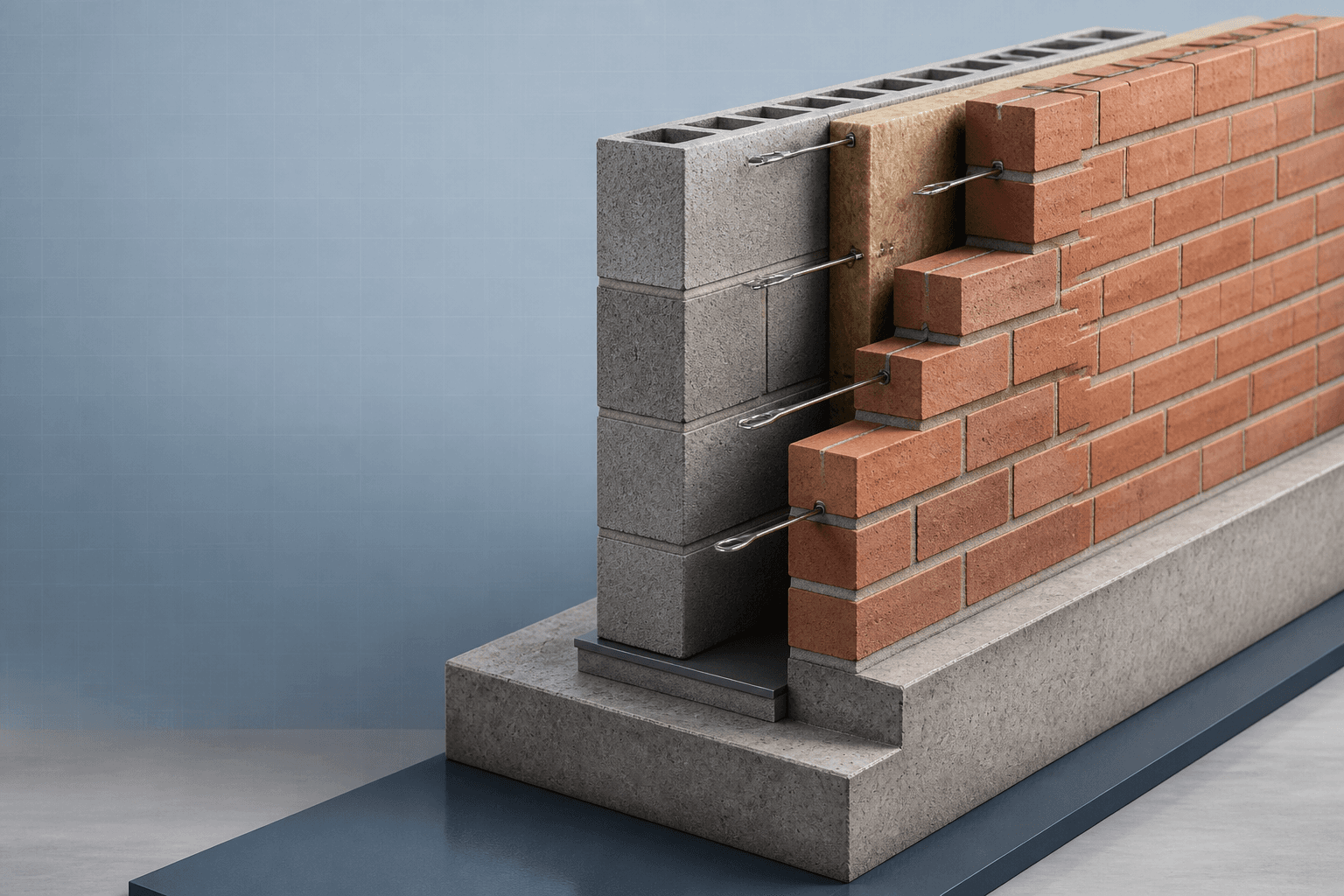
Masonry walls act as a building system. Some carry gravity actions, some form lateral load paths, and returns or cross-walls may provide restraint. Material capacity alone is insufficient if diaphragms, junctions, foundations or openings interrupt the assumed path.
5.2 NotationSource §5.2
| Symbol | Meaning | Unit |
|---|---|---|
| V_Ed / V_Rd | Design in-plane shear action / resistance | kN or kN/m |
| f_vk / f_vd | Characteristic / design masonry shear strength | N/mm² |
| σ_d | Design vertical compressive stress | N/mm² |
| M_Ed / M_Rd | Design overturning or lateral moment / flexural resistance | kNm/m |
| M_Rds | Cracked-section stability moment resistance | kNm/m |
| t, h, l | Thickness, height and length | mm or m |
5.3 Out-of-plane versus in-plane actionSource §5.3
- Out-of-plane panel action
- Wind bends the wall across its thickness; support, span and flexural strength govern.
- In-plane shear-wall action
- Horizontal force travels along the wall to foundations; shear, sliding and overturning govern.
5.4 Load path and wall-system behaviourSource §5.4
A typical path is external pressure or frame action → floor or roof diaphragm → shear wall or return → foundation. Every link must exist and be capable of transferring the action.
- Confirm sufficient wall continuity.
- Confirm diaphragm transfer to the wall line.
- Verify returns and cross-walls are bonded or tied.
- Check openings, chases and movement joints.
- Confirm foundation restraint and overturning resistance.
5.5 In-plane shear and slidingSource §5.5
Uses the effective wall length and a reviewed design shear strength.
The friction assumption, DPC type and reliable vertical compression at the interface are critical.
5.6 Returns, cross-walls and stiffeningSource §5.6
- Potentially useful
- Fully bonded or properly tied return; compatible loading and movement; junction unlikely to crack.
- Use conservatively
- Openings close to return; unbonded/touching walls; movement joints or chases interrupting the path.
5.7 Free-standing and boundary-wall stabilitySource §5.7
A free-standing wall acts as a cantilever from its base. The source presents a flexural-strength route and a cracked-section equilibrium route.
Limited compression contributes in the source teaching route; verify the applicable design basis.
The cracked-section stability moment may be more restrictive than the flexural-strength result.
5.8 When masonry should not be the assumed primary stability systemSource §5.8
| Condition | Why the simplified wall-line model is incomplete |
|---|---|
| Large openings | Interrupt effective wall length and force transfer. |
| Flexible diaphragm | May not distribute action to the selected wall. |
| Poor junctions | Unbonded or cracked returns do not provide full restraint. |
| Incomplete foundation model | Overturning and sliding cannot be confirmed. |
5.9 Shear and Stability CalculatorSource §5.9
Shear and Stability Calculator
Provide source-supported teaching checks for in-plane shear, sliding and boundary-wall flexural/cracked stability while clearly labelling the result as a concept check.
- Inputs
- Wall length/thickness · f_vd · V_Ed · N_Ed · Friction coefficient · Boundary height/thickness · Material strengths · Unit weight · Partial factors
- Outputs
- Shear resistance/utilisation · Sliding utilisation · Boundary-wall flexural capacity · Characteristic pressure capacity · Cracked stability moment
- Status states
- Concept check · Fail · Invalid input
- Validation
- Approved against the supplied worked-example results; project-specific verification remains required
Shear and Stability Calculator
Approved educational implementation reproducing the supplied source example.
Simplified shear and sliding checks pass; full building stability analysis is still required.
- Shear resistance
- 129.00 kN
- Shear utilisation
- 0.39
- Sliding utilisation
- 0.63
- Boundary-wall M_Rd
- 0.253 kNm/m
- Characteristic wind capacity
- 0.23 kN/m²
- Cracked stability moment
- 0.141 kNm/m
Calculation trail
V_Rd = f_vd t l = 129.00 kNSliding resistance = μ_f N_Ed = 80.00 kNM_Rd = (f_xd1 + σ_d)Z = 0.253 kNm/mM_Rds = N_id z = 0.141 kNm/m
5.10 WE-06 — Boundary-wall stabilitySource §5.10
WE-06 · MAS-WE-06 · Rev. C
Compare 105 mm and 220 mm thick, 1.20 m high free-standing walls using flexural capacity, then check cracked-section stability for the 105 mm wall.
- Design strengths
fd = 2.33/3.0 = 0.776; fxd1 = 0.30/2.70
fxd1 = 0.111 N/mm2 - Self-weight stress
σd = 1.20(22) = 26.4 kN/m2
0.0264 N/mm2 - 105 mm modulus
Z = 1000(1052)/6
1.838 × 106 mm3/m - 105 mm resistance
MRd = (0.111 + 0.0264)(1.838 × 10⁶)
0.253 kNm/m - 105 mm pressure capacity
WEd,cap = 2(0.253)/1.22; divide by 1.5
Wk,cap ≈ 0.23 kN/m2 · LOW - 220 mm comparison
Z = 8.067 × 10⁶; MRd = 1.109 kNm/m
Wk,cap ≈ 1.03 kN/m2 - Cracked-section force
Nid = 1.2(0.105)(22) = 2.77 kN/m; bci = 2.77/0.776
bci = 3.57 mm - Cracked moment
z = 50.7 mm; MRds = 2.77(0.0507)
0.140 kNm/m · more restrictive
Result. The 105 mm wall has very low lateral resistance and is governed by cracked-section stability. Increasing thickness to 220 mm greatly improves capacity; final design must include wind exposure, piers, foundations, movement joints and workmanship.
5.11 Chapter summarySource §5.11
Key points
- In-plane shear and out-of-plane bending are different behaviours.
- Diaphragms, junctions and foundations determine whether a wall system works.
- Free-standing walls are often governed by lateral stability.
- Simplified results must be labelled concept checks.
| Case | G_k | Q_k | W_k |
|---|---|---|---|
| Compression side · dead + imposed + wind | 1.35 | 1.50 | 0.75 |
| Compression side · alternative | 1.35 | 1.05 | 1.50 |
| Tension side · dead + wind | 1.00 | — | 1.50 |
Source references recorded by the supplied chapter
- EN 1996-1-1 ULS, shear, flexural and stability concepts
- EN 1990 Equation 6.10 teaching combinations
- Masonry Note Parts 1, 2 and 4
- Updated interactive book Chapter 05