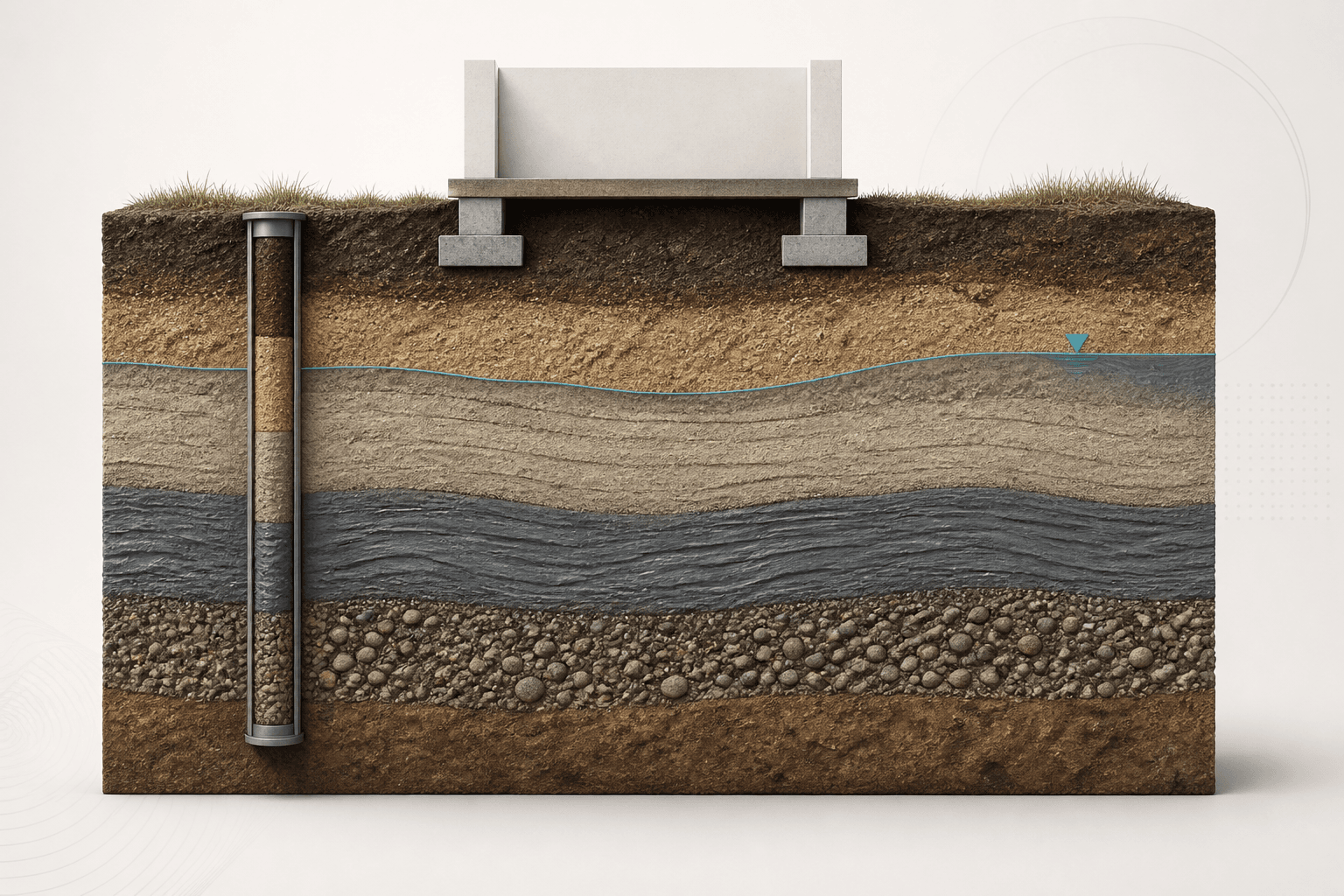
After this chapter, you should be able to
- Distinguish drained and undrained idealizations.
- Apply the Mohr–Coulomb effective-stress envelope.
- Select tests that represent the relevant stress path.
- Recognize scale, anisotropy and progressive-failure effects.
- Document a parameter-selection chain from evidence to design value.
Engineering context and evidenceSource §Lesson 06 · Engineering context and evidence · NHI-06-088 Chapters 2, 5 and 6
Shear strength is mobilized response, not an immutable label attached to a soil name. Parameter selection must match stress path, drainage, strain rate, stress level, fabric and the limit state. A calculation can be numerically correct yet conceptually wrong if it combines effective stresses with undrained total-stress parameters.
Core principles and terminologySource §Lesson 06 · Core principles and terminology · NHI-06-088 Chapters 2, 5 and 6
Drained loading allows pore pressures to dissipate sufficiently for effective-stress behaviour to be represented. Undrained loading generates pore-pressure response and is often assessed in total stress or with coupled effective-stress analysis. Peak, critical-state and residual strengths address different deformation histories and failure mechanisms.
- Effective friction angle, φ′
- Slope parameter of the adopted effective-stress failure envelope over the relevant stress range.
- Effective cohesion intercept, c′
- Intercept of a fitted effective-stress envelope; it may reflect true bonding, structure or fitting and needs justification.
- Undrained shear strength, su
- Total-stress strength measure for a stated loading, sampling and test condition.
- Stress path
- Sequence of stress states followed during loading, unloading and pore-pressure response.
Equations, conventions and valid useSource §Lesson 06 · Equations, conventions and valid use · NHI-06-088 Chapters 2, 5 and 6
Use normal effective stress on the candidate plane and parameters fitted for the relevant material, stress range and shearing condition.
This dimensionless teaching diagnostic compares mobilized to envelope shear stress. It is not a code-defined global factor of safety and must not replace the governing method.
Engineering workflowSource §Lesson 06 · Engineering workflow · NHI-06-088 Chapters 2, 5 and 6
- Define the construction stage, limit state, timescale and credible failure mechanism.
- Choose total- or effective-stress analysis and maintain that basis throughout.
- Review geology, fabric, discontinuities, stress history and sample quality.
- Select field or laboratory tests that reproduce the relevant drainage and stress path as closely as practicable.
- Plot data over the design stress range; examine scatter and alternative envelopes.
- Select representative parameters with explicit treatment of variability, bias and consequence.
- Check sensitivity, progressive failure, residual surfaces and construction observations.
| Question | Evidence to retain | Warning |
|---|---|---|
| Drainage condition | Loading time versus drainage response | Soil type alone does not decide it |
| Stress basis | Total or effective stress throughout | Never mix unmatched parameters |
| Strength state | Peak, critical or residual | Large displacement can govern |
| Anisotropy | Orientation and depositional fabric | Vertical specimens may not represent a slip surface |
Verified teaching exampleSource §Lesson 06 · Verified teaching example · NHI-06-088 Chapters 2, 5 and 6
Evaluate an effective-stress envelope point
For c′ = 5 kPa, φ′ = 30° and normal effective stress σ′n = 120 kPa, calculate the Mohr–Coulomb envelope shear stress.
- Angle
tan 30° = 0.57735
Friction component coefficient = 0.57735 - Friction component
120×0.57735
69.28 kPa - Envelope
τf = 5 + 69.28
τf = 74.28 kPa
Result. The fitted envelope gives τf = 74.28 kPa at σ′n = 120 kPa. It is valid only for the stated parameter basis and applicable stress range.
Mohr–Coulomb envelope point
Evaluate one effective-stress envelope point and show its cohesive and friction components.
- Inputs
- c′ in kPa · σ′n in kPa · φ′ in degrees
- Outputs
- Friction component · Envelope shear stress
- Status states
- Complete teaching case · Invalid or non-finite input · Outside stated method domain
- Validation
- Implemented against the supplied worked example; independent technical approval pending
Mohr–Coulomb Envelope Point
Evaluates one point on a stated linear effective-stress envelope and separates intercept and friction components.
The stated envelope gives τf = 74.28 kPa at σ′n = 120.00 kPa.
- Intercept component c′
- 5.00 kPa
- Friction component σ′n tan φ′
- 69.28 kPa
- Envelope shear stress τf
- 74.28 kPa
Show calculation trail
tan(30.00°) = 0.57735τf = c′+σ′n tanφ′ = 5.00+69.28 = 74.28 kPa
Failure modes and engineering judgementSource §Lesson 06 · Failure modes and engineering judgement · NHI-06-088 Chapters 2, 5 and 6
- Combining effective stress with undrained su.
- Selecting φ′ from a soil name without applicable test or correlation evidence.
- Forcing a non-zero c′ through scattered data without physical justification.
- Using peak strength on a pre-existing polished surface.
- Ignoring sample disturbance and stress-range dependence.
Key points
- Strength is conditional on stress path, drainage and deformation history.
- Stress variables and strength parameters must use the same basis.
- Test applicability and sample quality matter as much as arithmetic.
- Sensitivity studies should expose the consequences of plausible parameter ranges.
Source references recorded by the supplied chapter
- FHWA NHI-06-088, Soils and Foundations Reference Manual, Volume I, Chapters 2, 5 and 6.