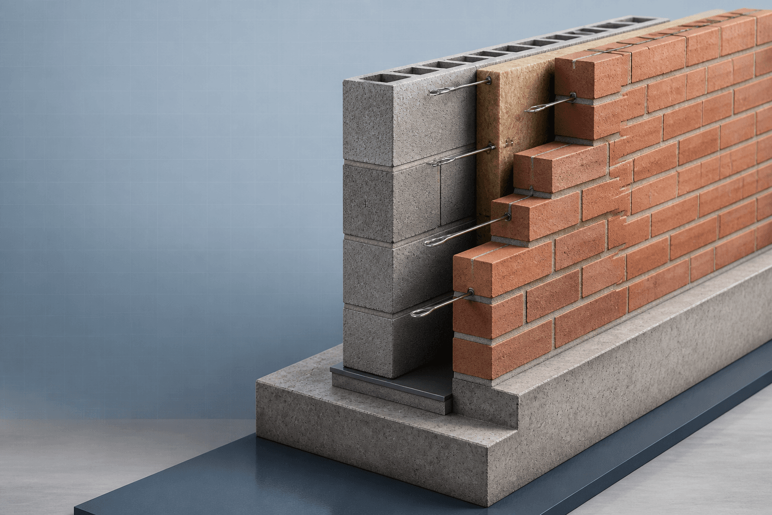
After this chapter, you should be able to
- Distinguish crushing-sensitive and buckling-sensitive behaviour.
- Calculate actions at top, mid-height and bottom.
- Select effective height and effective thickness.
- Apply minimum eccentricity and reduction factors.
- Report utilisation and the governing location.
2.1 Purpose and design questionSource §2.1
A vertically loaded masonry wall must not be checked by compression stress alone. The design must consider how load reaches the wall, how floors or roofs restrain it, and whether eccentricity and slenderness reduce usable resistance.
2.2 NotationSource §2.2
| Symbol | Meaning | Typical unit |
|---|---|---|
| N_Ed | Design vertical action applied to the wall | kN/m |
| N_Rd | Design vertical resistance | kN/m |
| h, h_ef | Clear and effective wall height | mm or m |
| t, t_ef | Wall and effective thickness | mm |
| e_i, e_m, e_init | End, mid-height and initial eccentricity | mm |
| Φ | Capacity-reduction factor for eccentricity and slenderness | — |
| f_k, f_d | Characteristic and design masonry compressive strength | N/mm² |
2.3 Behaviour under vertical loadingSource §2.3
A short wall is usually crushing-sensitive. A tall or slender wall may become unsafe before reaching crushing strength because eccentricity and deflection reduce resistance. Check the wall at top, bottom and mid-height.
For a one-metre wall strip, t is the structural thickness per metre run.
2.4 Vertical wall design procedureSource §2.4
| Step | Design action | Main output |
|---|---|---|
| 1 | Evaluate ULS floor, roof and wall self-weight actions. | Top, mid-height and bottom design actions |
| 2 | Determine effective height from floor/roof and side restraint. | Effective height |
| 3 | Determine effective thickness from wall form and valid stiffening assumptions. | Effective structural thickness |
| 4 | Check slenderness ratio. | Slenderness status |
| 5 | Calculate moments and eccentricities. | End and mid-height eccentricities |
| 6 | Obtain capacity-reduction factors. | End and mid-height Φ |
| 7 | Calculate resistance and compare with design action. | Utilisation and governing location |
2.5 Effective heightSource §2.5
Effective height controls the buckling-sensitive part of the check. Better top, bottom and side restraint produces a smaller effective height. The source teaching example uses 0.75 for reinforced-concrete slab restraint with small eccentricity; timber floors or weak restraint are normally more conservative.
Select ρ_n only from the applicable restraint condition and verified design source.
2.6 Effective thicknessSource §2.6
For a single-leaf wall, effective thickness is normally the actual structural masonry thickness. A coefficient for piers or stiffening may be used only where geometry, bonding, detailing and the load path justify it.
Do not include plaster as structural thickness unless the applicable method explicitly allows it.
2.7 Slenderness ratioSource §2.7
If exceeded, improve restraint or thickness, add valid stiffening, or use a more detailed method. Do not force a passing result.
2.8 Moments, axial loads and eccentricitySource §2.8
Floor reactions may introduce moment into the wall. Eccentricity is related to bending moment divided by vertical load, with allowances for initial eccentricity and lateral-load eccentricity where relevant.
For an internal loadbearing wall without lateral load, e_he may be zero.
The minimum eccentricity rule must also be checked.
2.9 Capacity-reduction factorSource §2.9
Used at top and bottom where end eccentricity is known.
The mid-height value is normally obtained from the applicable Annex G relationship or chart. The smallest relevant factor governs.
2.10 Vertical resistance checkSource §2.10
Normally reported per metre run of wall for this chapter.
| Governing problem | Possible response |
|---|---|
| High slenderness | Increase thickness, reduce clear height, add a valid stiffening wall or improve restraint. |
| High eccentricity | Improve bearing detail, reduce transferred moment or change wall layout. |
| Low material strength | Use suitable stronger units/mortar or change wall type. |
| High vertical action | Increase thickness, add designed piers or redistribute load. |
2.11 Vertical Wall Design CalculatorSource §2.11
Vertical Wall Design Calculator
Expose the effective-height, slenderness, eccentricity, reduction-factor and vertical-resistance trail at top, mid-height and bottom.
- Inputs
- Clear height · Height factor · Structural thickness · Characteristic strength · Material factor · Top/mid/bottom actions · Reviewed mid-height Φ
- Outputs
- Effective height · Slenderness · Eccentricity · Reduction factors · Design strength · Governing utilisation
- Status states
- Pass · Fail · Invalid input
- Validation
- Approved against the supplied worked-example results; project-specific verification remains required
Vertical Wall Design Calculator
Approved educational implementation reproducing the supplied source example.
The source-example wall satisfies the simplified vertical resistance checks.
- Effective height
- 2250 mm
- Slenderness hₑf/t
- 10.00
- Adopted eccentricity
- 11.25 mm
- End / mid-height Φ
- 0.90 / 0.85
- Design strength f_d
- 0.777 N/mm²
- Governing utilisation
- 0.92
Calculation trail
hₑf = 3.00 × 0.75 = 2250 mmλ = 2250 / 225 = 10.00e = max(hₑf/450, 0.05t) = 11.25 mmΦend = 1 − 2e/t = 0.90N_Rd,mid = 0.85 × 225 × 0.777 = 148.54 kN/m
2.12 WE-02 — Complete vertically loaded wallSource §2.12
WE-02 · MAS-WE-02 · Rev. B
Check a 225 mm masonry wall in a three-storey house supporting reinforced-concrete one-way slabs. Clear height is 3.0 m; the source uses reinforced-concrete restraint and no lateral-load eccentricity.
- ULS floor load
gk = 0.125(25) + 0.75 = 3.875 kN/m2; qEd = 1.35(3.875) + 1.5(2.0)
Design floor load = 8.23 kN/m2 - Load take-down
NEd,top = 121.81; NEd,mid = 132.94; NEd,bot = 144.08 kN/m
Bottom has the largest applied action - Effective geometry
hef = 0.75(3.0) = 2.25 m; tef = 225 mm
hef = 2250 mm; tef = 225 mm - Slenderness
hef/tef = 2250/225 = 10
10 ≤ 27 · PASS - Minimum eccentricity
einit = 2250/450 = 5.0 mm; emin = 0.05(225) = 11.25 mm
Adopt 11.25 mm - Reduction factors
Φtop = Φbot = 1 − 2(11.25)/225 = 0.90; Φmid ≈ 0.85
Smallest Φ = 0.85 - Design strength
fd = 2.33/3.0 = 0.776 N/mm2
Teaching material selection recorded - Resistance
NRd,mid = 0.85(225)(0.776) = 148.4; NRd,bot = 0.90(225)(0.776) = 157.1 kN/m
Governing utilisation ≈ 0.92 · PASS
Result. The source example passes. The bottom load gives the largest utilisation; mid-height remains important because slenderness and eccentricity control its reduction factor.
2.13 Chapter summarySource §2.13
Key points
- Check top, bottom and mid-height.
- Select effective height and thickness from real restraint and structural geometry.
- Apply minimum eccentricity and show reduction factors.
- Report the governing location and explain failures.
Source references recorded by the supplied chapter
- EN 1996-1-1 Clause 6.1.2.1 and Annex G concepts
- Masonry Note Part 2 Sections 3.1–3.10
- Updated interactive book Chapter 02