After this chapter, you should be able to
- Explain why masonry behaviour depends on units, mortar, bond and workmanship.
- Identify wall forms, unit category and unit group before calculation.
- Distinguish characteristic and design compressive and flexural strengths.
- Prepare a material data card for later masonry design checks.
- Recognise that the proposed calculator checks data completeness, not member adequacy.
1.1 Purpose of this chapterSource §1.1
This chapter builds the material understanding needed before member design is attempted. Later chapters require characteristic and design compressive strengths, flexural strengths, unit group, mortar class and partial-factor assumptions. The output is a reusable material data card.
1.2 What masonry means in structural designSource §1.2
Masonry is formed from artificial or natural units laid with mortar. It is commonly used for walls and columns carrying compression, and can also be used in arches, vaults and domes. The structural member is not the unit alone: behaviour depends on the unit, mortar, bond pattern, workmanship and support condition.
| Component | Role in design |
|---|---|
| Masonry unit | Provides most compressive resistance. Unit type and group affect fₖ. |
| Mortar joint | Transfers load between units and affects strength, deformation and durability. |
| Bond arrangement | Controls load distribution and interlocking between units. |
| Workmanship / execution | Affects partial-factor selection and reliability of the design assumptions. |
1.3 Limit state design ideaSource §1.3
Masonry is designed to satisfy ultimate limit states and serviceability limit states. Ultimate limit states concern collapse, loss of stability and structural failure. Serviceability limit states concern deflection, cracking, deformation and conditions affecting normal use or appearance.
E_d is the design effect of actions and R_d is the corresponding design resistance.
| Limit state | What it checks | Typical masonry example |
|---|---|---|
| ULS | Safety against collapse or failure. | Vertical wall resistance, bearing failure, or flexural failure under wind. |
| SLS | Performance during normal use. | Excessive slenderness, deflection, cracking, or movement-joint problems. |
1.4 Wall forms and bond arrangementsSource §1.4
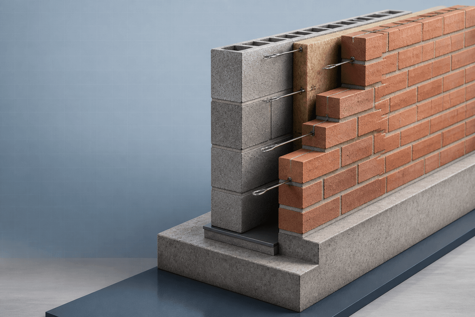
Define the wall form before calculations start. A single-leaf wall may normally be checked using its actual thickness. A cavity wall needs assumptions for leaf thickness, ties, load sharing and effective thickness. Veneered or faced walls should not be assumed to act as one structural wall unless connection details justify it.
- Single-leaf wall
- One structural leaf carrying vertical and/or lateral actions.
- Cavity wall
- Two leaves separated by a cavity and connected by ties.
- Faced or veneered wall
- Facing may be architectural unless structurally connected.
- Stiffened wall
- Receives restraint from returns, cross-walls or piers.
Bonding controls interlock and load spread. Stretcher, English and Flemish bond are common teaching examples. Poor bonding or poor workmanship reduces confidence in the design assumptions.
1.5 Masonry units: type, category and groupSource §1.5
Masonry units may be clay, aggregate concrete, autoclaved aerated concrete, calcium silicate, manufactured stone or natural stone. Eurocode-style design requires the unit category, unit group and declared compressive strength as well as the unit name.
- Category I
- Declared strength is controlled with higher confidence.
- Category II
- Uses a lower reliability assumption for declared strength.
- Natural stone
- Commonly treated as Category II unless data justify otherwise.
- Unit group
- Depends mainly on the percentage and orientation of holes or voids; it influences strength-equation constants and warnings.
| Requirement | Material | Group 1 | Group 2 | Group 3 | Group 4 |
|---|---|---|---|---|---|
| All holes (% gross volume) | Clay | ≤ 25 | > 25; ≤ 55 | ≥ 25; ≤ 70 | > 25; ≤ 70 |
| All holes (% gross volume) | Calcium silicate | ≤ 25 | > 25; ≤ 55 | Not used | Not used |
| All holes (% gross volume) | Aggregate concrete | ≤ 25 | > 25; ≤ 60 | > 25; ≤ 70 | > 25; ≤ 50 |
| Web / shell thickness (mm) | Clay | No requirement | ≥ 5 / ≥ 8 | ≥ 3 / ≥ 6 | ≥ 5 / ≥ 6 |
| Web / shell thickness (mm) | Calcium silicate | No requirement | ≥ 5 / ≥ 10 | Not used | Not used |
| Web / shell thickness (mm) | Aggregate concrete | No requirement | ≥ 15 / ≥ 18 | ≥ 15 / ≥ 15 | ≥ 20 / ≥ 20 |
| Combined web/shell thickness (% width) | Clay | No requirement | ≥ 16 | ≥ 12 | ≥ 12 |
| Combined web/shell thickness (% width) | Calcium silicate | No requirement | ≥ 20 | Not used | Not used |
| Combined web/shell thickness (% width) | Aggregate concrete | No requirement | ≥ 18 | ≥ 15 | ≥ 45 |
1.6 Mortar, bedding and joint assumptionsSource §1.6
Mortar type and strength class influence the characteristic compressive strength of masonry. M2, M4, M6 and M12 are common teaching classes. Bedding condition must also be known because full bedding and shell bedding can lead to different resistance assumptions.
- Use the mortar class matching the actual mix or specified product.
- Do not assume that high unit strength automatically gives high masonry strength.
- Require mortar class as a calculator input.
| Class | Cement : lime : sand | Cement : sand | Masonry cement C : sand | Masonry cement D : sand | Designation |
|---|---|---|---|---|---|
| M12 | 1 : (0 to ¼) : 3 | 1 : 3 | Not suitable | Not suitable | (i) |
| M6 | 1 : ½ : (4 to 4½) | 1 : (3 to 4) | 1 : (2½ to 3½) | 1 : 3 | (ii) |
| M4 | 1 : 1 : (5 to 6) | 1 : (5 to 6) | 1 : (4 to 5) | 1 : (3½ to 4) | (iii) |
| M2 | 1 : 2 : (8 to 9) | 1 : (7 to 8) | 1 : (5½ to 6½) | 1 : 4½ | (iv) |
1.7 Basic material behaviourSource §1.7
Masonry is strong in compression but weak in tension. Under compression, a mortar joint can deform laterally more than the unit. This creates transverse tensile stresses in the units and helps explain why masonry strength is not equal to unit strength alone.
1.8 Characteristic and design compressive strengthSource §1.8
Characteristic compressive strength may be obtained from tests. When test results are unavailable, it may be estimated from normalised unit strength and mortar strength using the Eurocode 6 relationship.
fₖ is characteristic masonry compressive strength; f_b is normalised mean unit strength; f_m is mortar compressive strength; K, α and β depend on the unit and mortar condition.
Select γ_M from the relevant National Annex and execution-control condition.
| Masonry unit | Group / orientation | General-purpose | Thin-layer | Lightweight 600–800 | Lightweight 800–1300 |
|---|---|---|---|---|---|
| Clay | Group 1 | 0.50 | 0.75 | 0.30 | 0.40 |
| Clay | Group 2 | 0.40 | 0.70 | 0.25 | 0.30 |
| Calcium silicate | Group 1 | 0.50 | 0.80 | No UK value | No UK value |
| Calcium silicate | Group 2 | 0.40 | 0.70 | No UK value | No UK value |
| Aggregate concrete | Group 1 | 0.55 | 0.80 | 0.45 | 0.45 |
| Aggregate concrete | Group 1 laid flat | 0.50 | 0.70 | 0.40 | 0.40 |
| Aggregate concrete | Group 2 | 0.52 | 0.76 | 0.45 | 0.45 |
| AAC | Group 1 | 0.55 | 0.80 | 0.45 | 0.45 |
| Manufactured stone | Group 1 | 0.45 | 0.75 | No UK value | No UK value |
| Dimensioned natural stone | Group 1 | 0.45 | No UK value | No UK value | No UK value |
1.9 Flexural strengths required laterSource §1.9
Laterally loaded masonry uses flexural strength. Two characteristic flexural strengths are needed because behaviour differs with the direction of cracking relative to bed joints.
- fₓₖ₁
- Characteristic flexural strength for a failure plane parallel to bed joints.
- fₓₖ₂
- Characteristic flexural strength for a failure plane perpendicular to bed joints.
- μ
- Orthogonal strength ratio used in panel design.
- fₓd
- Design flexural strength after applying the partial factor.
1.10 Basic material data card for later chaptersSource §1.10
Create the material data card before later calculations. It is reused for vertical wall resistance, lateral panel resistance, bearing checks, cavity-wall checks and combined loading.
| Data item | Required value | Used later for |
|---|---|---|
| Unit type and group | Clay / concrete / AAC / stone; source-defined group | K value, strength equations and warnings |
| Unit category | Category I or Category II | Material partial factor and reliability note |
| Mortar class | M2, M4, M6, M12 or project-defined | fₖ and flexural-strength lookup |
| fₖ | Characteristic compressive strength | Vertical resistance and arching checks |
| γ_M and f_d | Partial factor and design compressive strength | ULS resistance checks |
| fₓₖ₁ and fₓₖ₂ | Characteristic flexural strengths | Laterally loaded panel design |
| Execution class / National Annex | Class 1 or 2; selected National Annex | Partial factors and table selection |
1.11 Material Strength Data CalculatorSource §1.11
Material Strength Data Calculator
Generate the material data card used in following masonry checks.
- Inputs
- Normalised unit strength · Mortar strength · Reviewed K, α and β values · Material partial factor · Flexural strengths
- Outputs
- fₖ · f_d · fₓₖ₁ · fₓₖ₂ · Orthogonal ratio · Material-data summary
- Status states
- Complete data · Missing data · Not recommended for selected use
- Validation
- Approved against the supplied worked-example results; project-specific verification remains required
Material Strength Data Calculator
Approved educational implementation reproducing the supplied source example.
The source-example material card is complete. This is not a member adequacy check.
- Characteristic strength fₖ
- 2.34 N/mm²
- Design strength f_d
- 0.87 N/mm²
- Orthogonal ratio μ
- 0.33
- fₓₖ₁ / fₓₖ₂
- 0.30 / 0.90 N/mm²
Calculation trail
fₖ = 0.50 × 5.00^0.70 × 4.00^0.30 = 2.34 N/mm²f_d = 2.34 / 2.70 = 0.87 N/mm²μ = 0.30 / 0.90 = 0.33
1.12 WE-01 — Material Strength Data CardSource §1.12
WE-01 · MAS-WE-01 · Rev. A
Create a teaching material data card for Group 1 clay masonry units, Category I, normalised unit strength fb = 5.0 N/mm2, M4 general-purpose mortar with fm = 4.0 N/mm2, Class 2 execution control and water absorption greater than 12%.
- EN 1996-1-1 Cl. 3.6.1.2; UK NA values
Use teaching constants K = 0.50, α = 0.70 and β = 0.30.
Constants selected for Group 1 clay with general-purpose mortar. - EN 1996-1-1 Eq. 3.1
fk = 0.50 × 5.00.70 × 4.00.30
fk = 2.34 N/mm2 - EN 1996-1-1 Cl. 2.4 / UK NA Table NA.1
Use γM = 2.70 for this teaching case.
Material partial factor selected. - Design strength
fd = 2.34 / 2.70
fd = 0.87 N/mm2 - UK NA Table NA.6; Masonry Note Part 3
For clay units, water absorption > 12%, M4 mortar: use fxk1 = 0.30 and fxk2 = 0.90 N/mm2.
Characteristic flexural strengths selected. - EN 1996-1-1 Cl. 3.6.3
fxd1 = 0.30 / 2.70; fxd2 = 0.90 / 2.70
fxd1 = 0.11 N/mm2; fxd2 = 0.33 N/mm2
Result. Complete data: fk = 2.34 N/mm2, fd = 0.87 N/mm2, fxk1 = 0.30 N/mm2 and fxk2 = 0.90 N/mm2. This does not mean a wall passes; it means the material data needed for later member checks is ready.
1.13 Chapter summarySource §1.13
Key points
- Masonry strength depends on the unit, mortar, bond and workmanship—not unit strength alone.
- Create the material data card before vertical, lateral or bearing design.
- fₖ and f_d support compression-based checks; fₓₖ₁ and fₓₖ₂ support lateral flexural checks.
- The proposed calculator checks completeness and suitability of data, not member adequacy.
Source references recorded by the supplied chapter
- EN 1996-1-1 material clause anchors and Equation (3.1)
- UK National Annex Tables NA.1, NA.2, NA.4 and NA.6 as cited by the supplied source
- Masonry Note Part 1
- Masonry Note Part 3
- Updated interactive book structure and supporting Eurocode 6 guide references