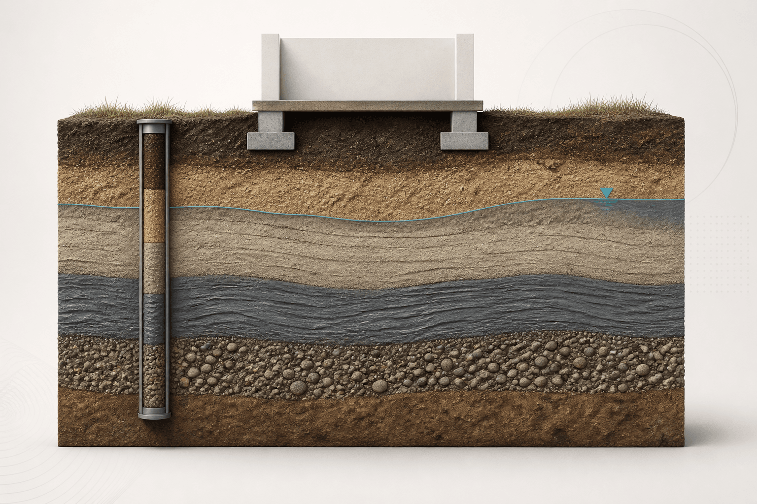
After this chapter, you should be able to
- Explain shaft and base components of axial resistance.
- Distinguish geotechnical resistance from structural resistance and settlement.
- Identify installation effects for driven and bored systems.
- Recognize group, downdrag and lateral-interaction issues.
- Build an acceptance plan linking observations and tests to decisions.
Engineering context and evidenceSource §Lesson 08 · Engineering context and evidence · NHI-06-089 Chapter 9 · NHI-18-024 · HIF-22-024
Deep foundations transfer actions through shaft resistance, base resistance or both, often across variable strata. The installed foundation is a construction product whose geometry and surrounding ground can differ from the analytical idealization. Design therefore needs a feedback loop between calculation, method, inspection, testing and acceptance.
Core principles and terminologySource §Lesson 08 · Core principles and terminology · NHI-06-089 Chapter 9 · NHI-18-024 · HIF-22-024
Driven systems displace or replace soil and can generate setup, relaxation, vibration and heave. Bored systems can suffer base debris, sidewall disturbance, slurry or casing effects and concrete defects. Load transfer mobilizes progressively with displacement, while groups may interact through shared stress zones and cap behaviour.
- Shaft resistance, Qs
- Axial resistance mobilized along the foundation–ground interface.
- Base resistance, Qb
- Axial resistance mobilized beneath the foundation toe or base.
- Downdrag
- Downward shaft load caused when surrounding ground settles relative to the deep foundation.
- Acceptance criterion
- Predefined evidence threshold and disposition process for confirming that installed work is suitable.
Equations, conventions and valid useSource §Lesson 08 · Equations, conventions and valid use · NHI-06-089 Chapter 9 · NHI-18-024 · HIF-22-024
The components require method-specific unit resistances, geometry and mobilization assumptions. Apply the governing resistance-factor or safety format separately and consistently.
These expressions assume uniform unit shaft and base resistance over ideal cylindrical geometry. Layered profiles require summation by interval and verified constructed dimensions.
Engineering workflowSource §Lesson 08 · Engineering workflow · NHI-06-089 Chapter 9 · NHI-18-024 · HIF-22-024
- Resolve axial, lateral, moment and uplift actions with load combinations and group layout.
- Build layer-by-layer strength, deformation, groundwater and obstruction profiles.
- Compare feasible foundation types against access, noise, spoil, durability and quality-control constraints.
- Calculate axial and lateral response with method-compatible parameters and factors.
- Check settlement, group interaction, downdrag, scour, cyclic effects and structural resistance.
- Define trial installations, records, integrity/load testing and acceptance thresholds before production.
- Reconcile as-built length, diameter, installation response and test results with the design model.
| Evidence | Question answered | Limitation |
|---|---|---|
| Installation log | Was the specified process followed? | Indirect indicator of capacity |
| Integrity test | Is a tested anomaly indicated? | Method resolution and interpretation vary |
| Static load test | What load–movement response occurred? | Represents tested foundation and setup time |
| Dynamic response | What installation/test response was measured? | Requires signal quality and specialist interpretation |
Verified teaching exampleSource §Lesson 08 · Verified teaching example · NHI-06-089 Chapter 9 · NHI-18-024 · HIF-22-024
Separate shaft and base components
For an ideal 0.60 m diameter, 15 m long shaft, use uniform fs = 45 kPa and qb = 3500 kPa solely to illustrate component arithmetic.
- Shaft area
As = π×0.60×15
As = 28.274 m2 - Shaft resistance
Qs = 45×28.274
Qs = 1272.3 kN - Base resistance
Qb = 3500×π×0.602/4
Qb = 989.6 kN - Nominal sum
Qu = 1272.3 + 989.6
Qu = 2261.9 kN
Result. The idealized nominal components sum to 2261.9 kN. No design resistance, settlement adequacy or acceptance follows from this arithmetic alone.
Failure modes and engineering judgementSource §Lesson 08 · Failure modes and engineering judgement · NHI-06-089 Chapter 9 · NHI-18-024 · HIF-22-024
- Using nominal calculated resistance directly as an allowable or factored design resistance.
- Assuming full shaft and base components mobilize at the same displacement.
- Ignoring construction-method effects when choosing unit resistance.
- Treating an integrity test as a direct capacity test.
- Failing to predefine how anomalous records will be investigated and accepted.
Key points
- Deep foundations are designed and verified as installed systems.
- Shaft, base, structural and movement checks must remain distinct.
- Installation method changes both ground response and quality risks.
- Acceptance criteria should be planned before production work begins.
Source references recorded by the supplied chapter
- FHWA NHI-06-089, Soils and Foundations Reference Manual, Volume II, Chapter 9.
- FHWA-NHI-18-024, Drilled Shafts: Construction Procedures and LRFD Design Methods.
- FHWA-HIF-22-024, Acceptance Procedures for Structural Foundations of Transportation Structures.