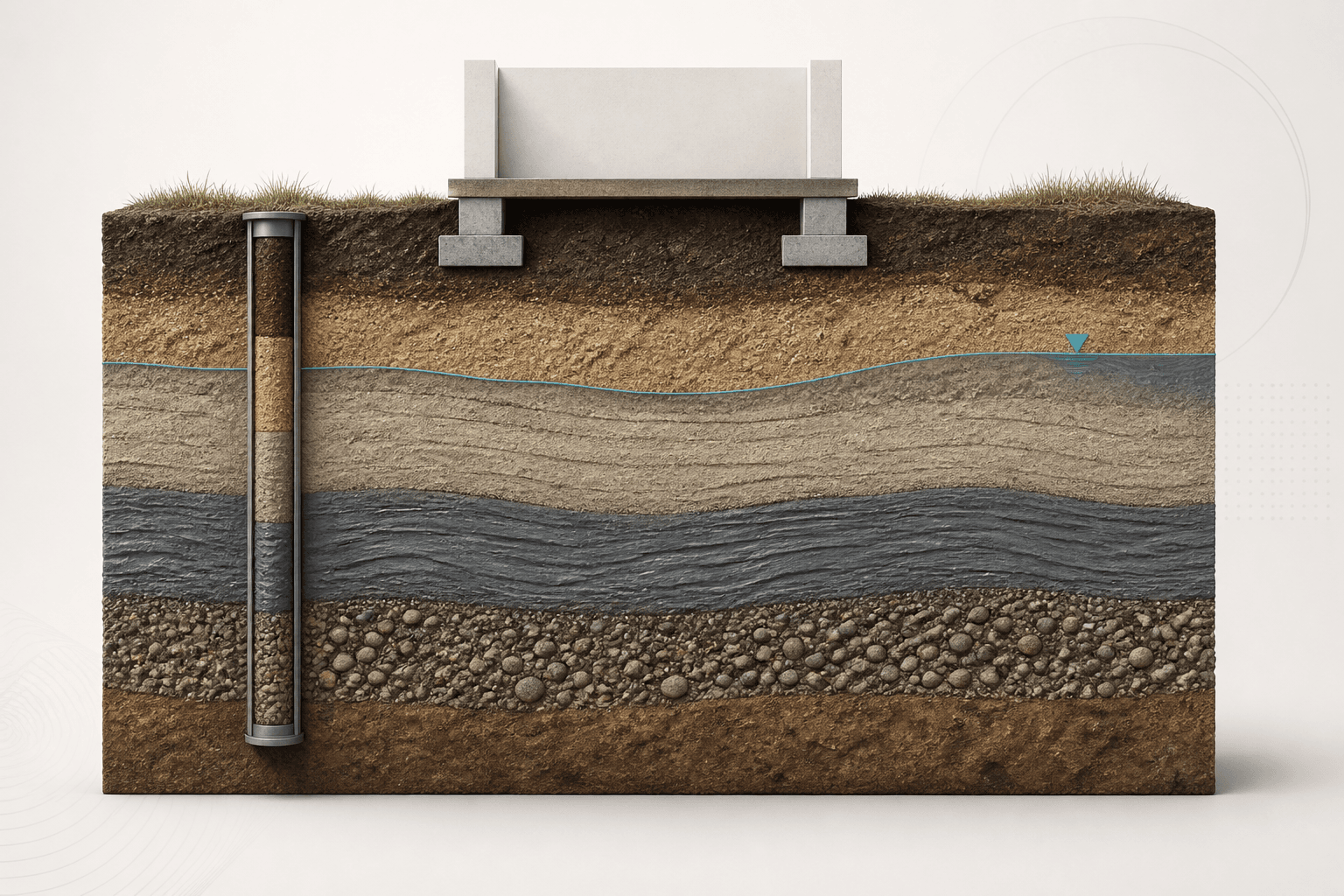
After this chapter, you should be able to
- Explain the effective-stress principle for saturated soils.
- Construct a vertical stress profile with a water table.
- Calculate hydrostatic pore pressure and effective stress.
- Explain how seepage gradients alter stress and stability.
- Identify assumptions that a one-dimensional profile cannot represent.
Engineering context and evidenceSource §Lesson 04 · Engineering context and evidence · NHI-06-088 Chapters 2 and 5
The skeleton of a saturated soil carries effective stress while pore water carries pressure. Changes in load or water pressure can therefore alter deformation and strength even when total overburden is unchanged. Stress profiles must state ground level, strata, unit weights, water levels and whether pressures are hydrostatic or measured.
Core principles and terminologySource §Lesson 04 · Core principles and terminology · NHI-06-088 Chapters 2 and 5
Downward and upward seepage change hydraulic head through the soil. Upward gradients reduce effective stress and can lead to boiling, heave or internal erosion in susceptible ground; downward gradients increase effective stress. Transient drawdown is especially important because soil and water pressures may not adjust at the same rate.
- Total stress, σ
- Stress from the total weight and applied loads across the considered plane.
- Pore-water pressure, u
- Pressure carried by water in the voids, relative to the chosen datum and pressure reference.
- Effective stress, σ′
- Stress associated with the soil skeleton in the saturated-soil idealization.
- Hydraulic gradient, i
- Head loss or gain per unit flow length, with direction explicitly defined.
Equations, conventions and valid useSource §Lesson 04 · Equations, conventions and valid use · NHI-06-088 Chapters 2 and 5
Use consistent normal-stress and pressure signs. The simple saturated-soil relation does not by itself describe unsaturated suction or soil structure.
hw is vertical depth below a hydrostatic water surface when elevation head is used conventionally. Artesian or perched conditions need their actual piezometric level.
The body-force representation helps explain how seepage direction modifies the soil skeleton. It is not a complete piping or filter assessment.
Engineering workflowSource §Lesson 04 · Engineering workflow · NHI-06-088 Chapters 2 and 5
- Set an elevation datum and divide the profile where strata, unit weight or water conditions change.
- Calculate total stress incrementally from unit weights and surcharge.
- Establish hydrostatic, perched, artesian or measured piezometric conditions.
- Calculate pore pressure at each elevation with a consistent pressure datum.
- Subtract u from σ at matching locations and check continuity or justified jumps.
- Evaluate how construction, pumping, flooding and rapid drawdown change the two profiles.
- Use flow analysis, filters and monitoring where a one-dimensional hydrostatic model is inadequate.
| Input | Required record | Sensitivity question |
|---|---|---|
| Unit weight | Bulk, saturated or buoyant basis | Does the stratum vary? |
| Water level | Date, instrument and elevation | Is it seasonal or confined? |
| Surcharge | Magnitude, footprint and timing | Is stress distribution one-dimensional? |
| Seepage | Boundary heads and flow direction | Could gradients localize at an exit? |
Verified teaching exampleSource §Lesson 04 · Verified teaching example · NHI-06-088 Chapters 2 and 5
Vertical stress below a water table
At 8 m depth, the water table is at 3 m. Use γmoist = 18 kN/m3 above it, γsat = 20 kN/m3 below it and γw = 9.81 kN/m3. Ignore capillarity and surface surcharge.
- Total vertical stress
σv = 3×18 + 5×20
σv = 154.0 kPa - Hydrostatic pressure
u = 5×9.81
u = 49.05 kPa - Effective stress
σ′v = 154.0 − 49.05
σ′v = 104.95 kPa
Result. At 8 m depth, the stated one-dimensional hydrostatic model gives σv = 154.0 kPa, u = 49.05 kPa and σ′v = 104.95 kPa.
Two-layer hydrostatic stress profile
Check total, pore and effective stress at a depth below a stated water table.
- Inputs
- Depth and water-table depth · Moist and saturated unit weights · Water unit weight and surface surcharge
- Outputs
- Total vertical stress · Pore-water pressure · Effective vertical stress
- Status states
- Complete teaching case · Invalid or non-finite input · Outside stated method domain
- Validation
- Implemented against the supplied worked example; independent technical approval pending
Two-Layer Hydrostatic Effective Stress
A one-dimensional profile check with one water table, hydrostatic pressure and a uniform surface surcharge.
At 8.00 m, the hydrostatic effective vertical stress is 104.95 kPa.
- Depth below water table
- 5.00 m
- Total vertical stress σv
- 154.00 kPa
- Pore-water pressure u
- 49.05 kPa
- Effective vertical stress σ′v
- 104.95 kPa
Show calculation trail
σv = q + γmoist zw + γsat(z−zw) = 154.00 kPau = γw(z−zw) = 49.05 kPaσ′v = σv−u = 104.95 kPa
Failure modes and engineering judgementSource §Lesson 04 · Failure modes and engineering judgement · NHI-06-088 Chapters 2 and 5
- Using submerged unit weight to calculate total stress and subtracting pore pressure again.
- Measuring water depth from the wrong datum.
- Assuming a standpipe reading is hydrostatic across every layer.
- Ignoring short-term pore-pressure response to loading or drawdown.
- Using effective stress without matching the drainage basis of strength parameters.
Key points
- Effective stress links loading and pore pressure to soil-skeleton response.
- Total and pore-pressure profiles must share the same location and datum.
- Seepage direction changes effective stress and can create exit hazards.
- Transient water conditions may govern even when the final state appears safe.
Source references recorded by the supplied chapter
- FHWA NHI-06-088, Soils and Foundations Reference Manual, Volume I, Chapters 2 and 5.